Signal Integrity
Signal integrity (SI) is the branch of electrical design concerned with the error free transmission of digital signals through an analog medium.
All transmission mediums contain various impairment mechanisms such as loss, noise, delay, dispersion and distortion which affects the signals they are passing causing errors in decoding and synchronisation.
In digital systems, the signal frequencies have been rapidly increasing into the Gbps range which has meant that digital engineers are having to take into account discontinuity effects which have previously been the domain of RF engineering.
In SI engineering, the task is to minimize these signal distortion effects such that the transmitted data arrives at its end point in a condition that the original signal can be reconstructed and synchronised with time dependant data transmitted via other signal paths (such as bus systems).
Assessing the signals condition at the end point is most naturally viewed in the time domain however the signal path is most naturally modelled and measured in the frequency domain (using measurement devices such as vector network analysers (VNA) and S-parameter techniques).
One problem with using RF frequency domain techniques is that, although it is very fast, the resultant output is designed to show a paths network response, it does not usually include signal information.
To allow the effect of a path on a time variant signal to be assesed, digital signal processing (DSP) techniques, such as forier transforms and convolution, are combined with RF techniques to view the effects on generated signals through a measured or modelled path in the time domain.
The SI pack
Both SPsim and SPview includes a design and measurement tool set to generate the typical SI measurements and circuit methodolgies to allow signal paths to be created, tuned and optimised for best performance.
Existing hardware can be analysed using multi-port VNA measurement data which can be pre-existing (SnP format files) or created using SPsims integrated S-parameter capture system. The resultant data can be drag and dropped on to schematics, measured and/or integrated with simulated equalisation networks.
The measurement suite includes Mixed Mode S-parameter measurements (a technique for mapping the single ended measurements made by RF VNA's or simulators into common and differential modes), signal waveform generation and time domain transforms (including eye diagrams) for viewing the data in a more human friendly form.
The SI plotter tool
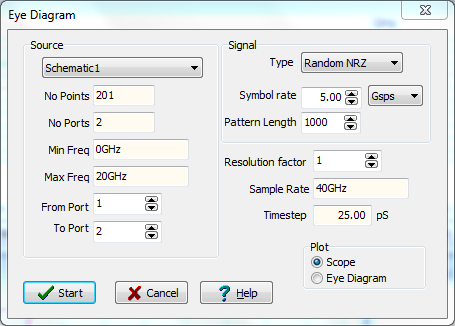
Apart from the integrated measurements system, the SI pack also includes a stand alone tool for generating SI plots from loaded source data.

The SI tool dialog screen.
Plot types
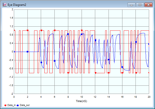
The plotter produces two graph type...The first is the Scope plot which is a straight oscilloscope type display of the input and output waveforms of the
analysed path.
The through path delay can be clearly displayed in this chart.

Waveform plottng using Scope.
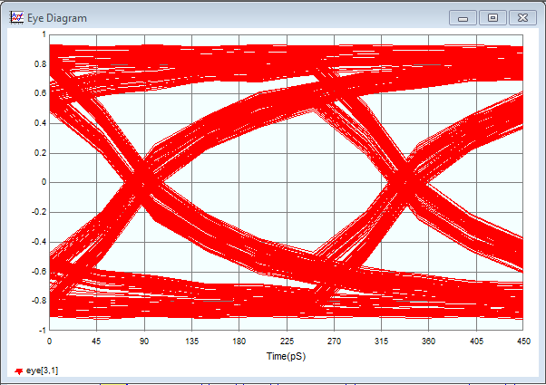
The second is the Eye Diagram plot which is the time sliced display of the output waveform of the
analysed path.
The eye aperture properties can be discerned from this plot.

Waveform plottng in Eye mode.
